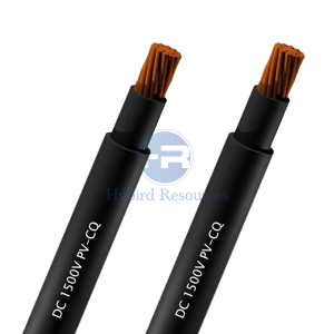
PV-CC DC1500V JCS 4517 Solar Wire
PV-CC DC1500V JCS 4517 Solar Wire Application
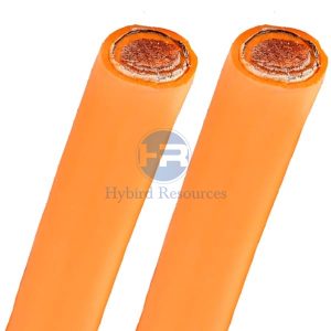
These PV-CC cables have superior environmental performance in terms of weather, heat and cold resistance, and are best suited for cabling in solar power generation systems. This cable is sunlight, ozone, UV, and moisture resistant. Photovoltaic Wire (PV Wire) may be used as wiring for solar panels, as the interconnection wiring of grounded and ungrounded photovoltaic power systems.
Characteristic:
Electron-beam cross-linked compounds; UV, ozone and hydrolysis resistant; High temperature resistant, the materials do not melt or flow; Good cold flexibility; Very long service life>25 years at 90℃; Compatible to all popular connectors
PV-CC DC1500V JCS 4517 Solar Wire Construction
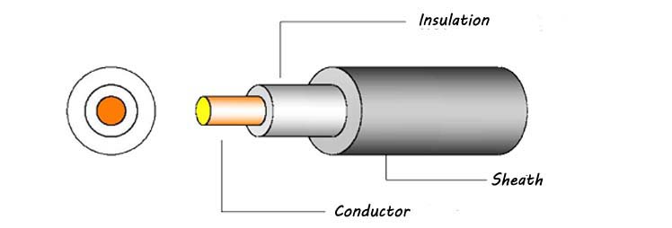
| Conductor material: | Bare/Tinned copper wire strands |
| Insulation: | XLPE compound Comply with RoHS |
| Insulation: | XLPE compound,Flame retardant,Comply with RoHS,Color:Black |
PV-CC DC1500V JCS 4517 Solar Wire Technical Data
| Rated Voltage U | DC 1500V |
| Test Voltage U | No breakdown at 6.5KA (AC), 50Hz, 5min, 20 ±5 ℃/ 15KA (DC), 5min, 20 ±5 ℃ |
| Bending Radius | Fixed installation>4D; Occasionally moved>5D |
| Rated Temperature | -40℃ to 90℃ Max. conductor temperature: 125 ℃ Allowable short circuit temperature 200 ℃ in 5 seconds |
| Flame Test | JIS C 3665-1-2(Whole wire) |
| Relative Permitivity | UL854 |
| High temp,humidity resistance | JIS C 60068-2-78,JIS C 3660-1-1 |
| UV Resistance | JIS C 7350-1,2 |
| Dynamic Penetration test | JIS G 0203 |
| The gas evolved during combustion | JIS C 3666-2 |
| Low temp impact | JIS C 3660-1-4 |
PV-CC DC1500V JCS 4517 Solar Wire Specification
| Cross Section | Conductor Construction | Conductor Stranded OD. | Cable OD. | Conductor Max. Resistance AT 20℃ | Insulation Resistance |
| (mm2) | (n/mm) | (mm) | (mm) | (Ω/km) | MΩ.km |
| 2 | 7/0.60 | 1.8 | 5.7 | 9.24 | 1000 |
| 3.5 | 7/0.80 | 2.4 | 6.3 | 5.2 | 1000 |
| 5.5 | 7/1.00 | 3 | 7.1 | 3.33 | 1000 |
| 8 | 7/1.20 | 3.6 | 7.8 | 2.31 | 1000 |
DISCLAIMER: This is just part of the standard parameters of our products. Please contact our Engineer if you need more. And the information contained within this webpage is for guidance only and is subject to change without notice or liability. All dimensions and specifications are nominal and are subject to normal manufacturing tolerances. All pictures shown are for illustration purposes only. The actual product may vary. All the information is provided in good faith and is believed to be correct at the time of publication.