Type G Round Portable Power Mining Cable 2kV
Type G Round Portable Power Mining Cable 2kV Application
Type G Round Portable Power and Mining Cable 600/2000V is intended for Industrial and light-to-medium mining, Heavy-duty service as power supply cable, Mobile and portable electrical equipment,3 phase AC system where grounding is required.
These flat parallel cables are designed for use on D.C. off-track mining equipment, such as D.C. shuttle cars, drills, cutting and loading machines.
This Type G Round portable mining cable has excellent impact and abrasion resistance,and withstand exposure to oil, acids, alkalies, heat, moisture and most chemicals,Indent printed for easy identification Rope lay stranding for maximum flex life,cable core bound for superior flexibility and toughness.
Type G Round Portable Power Mining Cable 2kV Standard
ICEA S-75-381/NEMA WC 58
ASTM B 172
ASTM B 33
CAN/CSA C22.2 No. 96
Type G Round Portable Power Mining Cable 2kV Construction
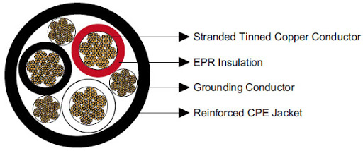
| Conductor: | coated annealed copper, bunched wires, rope-lay-stranded per ASTM B172 |
| Insulation: | Ethylene propylene rubber (EPR) |
| Jacket: | Chlorinated Polyethylene (CPE), Black |
Options:
Other jacket materials such as CSP/PCP/NBR/PVC are available upon request.
Two-layer jacket with reinforcing fiber between the two layers can be offered as an option.
Type G Round Portable Power Mining Cable 2kV Specification
| Construction | No. of Strands | Grounding Conductor Size |
Nominal Insulation Thickness |
Nominal Overall Diameter |
Nominal Weight |
Ampacity |
| No. of cores×AWG/kcmil | – | AWG/kcmil | mm | mm | kg/km | A |
| 2×8 | 133 | 10 | 1.5 | 20.6 | 736 | 72 |
| 2×6 | 259 | 10 | 1.5 | 23.6 | 967 | 95 |
| 2×4 | 259 | 8 | 1.5 | 27.4 | 1399 | 127 |
| 2×2 | 259 | 6 | 1.5 | 32.3 | 2023 | 167 |
| 2×1 | 259 | 5 | 2 | 36.6 | 2574 | 191 |
| 2×1/0 | 259 | 4 | 2 | 38.6 | 2976 | 217 |
| 2×2/0 | 259 | 3 | 2 | 41.9 | 3333 | 250 |
| 2×3/0 | 259 | 2 | 2 | 45 | 4255 | 286 |
| 2×4/0 | 259 | 1 | 2 | 48.8 | 5207 | 328 |
| 3×8 | 133 | 10 | 1.5 | 23.1 | 878 | 59 |
| 3×6 | 168 | 10 | 1.5 | 25.7 | 1131 | 79 |
| 3×4 | 259 | 8 | 1.5 | 29.7 | 1592 | 104 |
| 3×3 | 329 | 8 | 1.5 | 31.5 | 1904 | 120 |
| 3×2 | 259 | 8 | 1.5 | 34 | 2276 | 138 |
| 3×1 | 329 | 7 | 2 | 38.4 | 2812 | 161 |
| 3×1/0 | 259 | 6 | 2 | 41.9 | 3452 | 186 |
| 3×2/0 | 329 | 5 | 2 | 44.5 | 4017 | 215 |
| 3×3/0 | 413 | 4 | 2 | 48 | 4865 | 249 |
| 3×4/0 | 532 | 3 | 2 | 51.8 | 5907 | 287 |
| 3×250 | 608 | 2 | 2.4 | 60.7 | 7558 | 320 |
| 3×300 | 741 | 1 | 2.4 | 65 | 9046 | 357 |
| 3×350 | 855 | 1 | 2.4 | 68.1 | 10623 | 394 |
| 3×400 | 988 | 1/0 | 2.4 | 71.6 | 11575 | 430 |
| 3×500 | 1221 | 2/0 | 2.4 | 77 | 13487 | 487 |
| 4×6 | 259 | 12 | 1.5 | 27.9 | 1354 | 72 |
| 4×4 | 412 | 10 | 1.5 | 32.3 | 2050 | 93 |
| 4×2 | 259 | 9 | 1.5 | 37.6 | 2848 | 122 |
| 4×1 | 331 | 8 | 2 | 42.7 | 3438 | 143 |
| 4×1/0 | 414 | 7 | 2 | 45.5 | 4181 | 165 |
| 4×2/0 | 522 | 6 | 2 | 49 | 4840 | 192 |
| 4×3/0 | 658 | 5 | 2 | 52.6 | 6099 | 221 |
| 4×4/0 | 829 | 4 | 2 | 57.4 | 7327 | 255 |
| 4×250 | 973 | 3 | 2.4 | 67.6 | 9016 | 280 |
| 4×350 | 1361 | 1 | 2.4 | 75.7 | 12090 | 335 |
| 4×500 | 1921 | 1/0 | 2.4 | 86.4 | 16006 | 395 |
Ampacity-Based on a conductor temperature of 90℃ and an ambient air temperature of 40℃, per ICEA S-75-381.
Note: This is just part of the standard parameters of our products. Please contact our Engineer if you need more. And the information contained within this webpage is for guidance only and is subject to change without notice or liability. All dimensions and specifications are nominal and are subject to normal manufacturing tolerances. All pictures shown are for illustration purposes only. The actual product may vary. All the information is provided in good faith and is believed to be correct at the time of publication.