P5 BFOU Fire Resistant Offshore Power Cable 0.6/1KV
P5 BFOU Fire Resistant Offshore Power Cable 0.6/1KV Application
These P5 BFOU 0.6/1KV cables are flame retardant, low smoke, halogen-free and mud resistant, used for fixed installation for power transmission and lighting&Control in explosion risk and safe area on Drilling ships, drilling platforms ( jack-up, semi-submersible), Production Platforms ( TLP, semi-submersible, SPAR, fixed platforms) and FPSO/FSO.
P5 BFOU Fire Resistant Offshore Power Cable 0.6/1KV Standards
| Design | IEC60092-353 NEK606 |
| Construction | IEC60092-353 |
| Conductor | IEC60228 |
| Insulation | IEC60092-351 |
| sheathed | IEC60092-359 |
| Flame Retardant | IEC 60332-1,IEC60332-3-22 |
| Smoke Density | IEC61034 |
| Fire Resistant | IEC60331 |
| Halogen Index | IEC60754 |
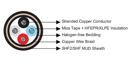
P5 BFOU Fire Resistant Offshore Power Cable NEK606 0.6/1KV Construction
| Classification | Code | Construction details |
| Conductor | Tinned Annealed Stranded Copper Wire | |
| Insulation | B | Mica Tape + EPR/XLPE |
| Bedding/Inner Covering | F | Halogen-free compound SHF1 |
| Armor | O | Tinned Copper wire braided |
| Outer Sheath | U | Halogen-free Thermosetting compound |
P5 BFOU Fire Resistant Offshore Power Cable NEK606 0.6/1KV Electrical Data
| Nominal Cross Section Area | Nominal Conductor Diameter |
Maximum DC Resistant @20℃ |
Continuous Current Rating@45℃ 1 Core |
Continuous Current Rating@45℃ 2 Core |
Continuous Current Rating@45℃ 3&4 Core |
Short Circuit Current 1s |
| mm² | mm | Ω/km | A | A | A | A |
| 1.5 | 1.6 | 12.2 | 23 | 20 | 16 | 210 |
| 2.5 | 2.1 | 7.56 | 30 | 26 | 21 | 360 |
| 4 | 2.6 | 4.7 | 40 | 34 | 28 | 570 |
| 6 | 3.2 | 3.11 | 52 | 44 | 36 | 860 |
| 10 | 4 | 1.84 | 72 | 61 | 50 | 1430 |
| 16 | 5.1 | 1.16 | 96 | 82 | 67 | 2290 |
| 25 | 6.5 | 0.734 | 127 | 108 | 89 | 3580 |
| 35 | 7.4 | 0.529 | 157 | 133 | 110 | 5010 |
| 50 | 8.7 | 0.391 | 196 | 167 | 137 | 7150 |
| 70 | 10.3 | 0.27 | 242 | 206 | 169 | 10020 |
| 95 | 12.2 | 0.195 | 293 | 249 | 205 | 13590 |
| 120 | 13.8 | 0.154 | 339 | 288 | 237 | 17170 |
| 150 | 15.1 | 0.126 | 389 | 331 | 272 | 21460 |
| 185 | 17 | 0.1 | 444 | 444 | 311 | 26470 |
| 240 | 19.6 | 0.0762 | 522 | 444 | 365 | 34340 |
| 300 | 21.9 | 0.0607 | 601 | 511 | 421 | 42930 |
| 400 | 24.6 | 0.0475 | 690 | 587 | 483 | 57230 |
| 630 | 32.5 | 0.0286 | 890 | 757 | 623 | 90140 |
P5 BFOU Fire Resistant Offshore Power Cable NEK606 0.6/1KV Specification
| Construction
No. of cores× Cross section |
Nominal Insulation
Thickness |
Nominal Sheath
Thickness (mm) |
Nominal Overall
Diameter |
Nominal
Weight |
|
| NO*mm2 | mm | Inner | Outer | mm | kg/km |
| 1×1.5 | 1 | 1.1 | 1.1 | 9.3 | 145 |
| 1×2.5 | 1 | 1.1 | 1.1 | 9.7 | 160 |
| 1×4 | 1 | 1.1 | 1.1 | 10.4 | 220 |
| 1×6 | 1 | 1.1 | 1.1 | 10.9 | 250 |
| 1×10 | 1 | 1.1 | 1.2 | 12.7 | 310 |
| 1×16 | 1 | 1.1 | 1.2 | 13.9 | 390 |
| 1×25 | 1.2 | 1.1 | 1.3 | 16.3 | 585 |
| 1×35 | 1.2 | 1.1 | 1.3 | 17.2 | 690 |
| 1×50 | 1.4 | 1.1 | 1.4 | 19 | 890 |
| 1×70 | 1.4 | 1.1 | 1.4 | 20.6 | 1110 |
| 1×95 | 1.6 | 1.1 | 1.5 | 23.1 | 1440 |
| 1×120 | 1.6 | 1.2 | 1.6 | 25 | 1735 |
| 1×150 | 1.8 | 1.2 | 1.7 | 27 | 2060 |
| 1×185 | 2 | 1.2 | 1.7 | 29.4 | 2545 |
| 1×240 | 2.2 | 1.2 | 1.8 | 32.6 | 3170 |
| 1×300 | 2.4 | 1.2 | 1.9 | 35.3 | 3910 |
| 1×400 | 2.4 | 1.4 | 2.1 | 41 | 5100 |
| 1×630 | 2.8 | 1.4 | 2.3 | 48.5 | 7660 |
| 2×1.5 | 1 | 1.1 | 1.2 | 14.2 | 310 |
| 2×2.5 | 1 | 1.1 | 1.3 | 15.1 | 360 |
| 2×4 | 1 | 1.1 | 1.3 | 16.6 | 470 |
| 2×6 | 1 | 1.1 | 1.4 | 17.9 | 555 |
| 2×10 | 1 | 1.1 | 1.4 | 19.9 | 705 |
| 2×16 | 1 | 1.1 | 1.5 | 22.5 | 985 |
| 2×25 | 1.2 | 1.2 | 1.6 | 26.4 | 1360 |
| 2×35 | 1.2 | 1.2 | 1.7 | 28.4 | 1620 |
| 2×50 | 1.4 | 1.2 | 1.9 | 32.4 | 2290 |
| 2×70 | 1.4 | 1.2 | 2.1 | 38 | 3260 |
| 2×95 | 1.6 | 1.2 | 2.3 | 41.6 | 3910 |
| 2×120 | 1.6 | 1.4 | 2.4 | 45.3 | 4710 |
| 2×150 | 1.8 | 1.4 | 2.6 | 49.7 | 5670 |
| 2×185 | 2 | 1.4 | 2.7 | 54.3 | 6840 |
| 2×240 | 2.2 | 1.6 | 3 | 61.5 | 8790 |
| 2×300 | 2.4 | 1.6 | 3.2 | 67.8 | 10630 |
| 3×1.5 | 1 | 1.1 | 1.3 | 14.8 | 345 |
| 3×2.5 | 1 | 1.1 | 1.3 | 16.2 | 445 |
| 3×4 | 1 | 1.1 | 1.3 | 17.4 | 530 |
| 3×6 | 1 | 1.1 | 1.4 | 18.7 | 635 |
| 3×10 | 1 | 1.1 | 1.5 | 21.1 | 830 |
| 3×16 | 1 | 1.1 | 1.5 | 23.7 | 1160 |
| 3×25 | 1.2 | 1.2 | 1.7 | 28.1 | 1640 |
| 3×35 | 1.2 | 1.2 | 1.8 | 30.2 | 1980 |
| 3×50 | 1.4 | 1.2 | 2 | 34.3 | 2750 |
| 3×70 | 1.4 | 1.2 | 2.2 | 39 | 3675 |
| 3×95 | 1.6 | 1.4 | 2.4 | 44.7 | 4955 |
| 3×120 | 1.6 | 1.4 | 2.5 | 48.3 | 6035 |
| 3×150 | 1.8 | 1.4 | 2.7 | 53.2 | 7355 |
| 3×185 | 2 | 1.6 | 2.9 | 59.5 | 9025 |
| 3×240 | 2.2 | 1.6 | 3.2 | 66.5 | 11590 |
| 3×300 | 2.4 | 1.8 | 3.4 | 72.6 | 13740 |
| 4×1.5 | 1 | 1.1 | 1.3 | 16.4 | 400 |
| 4×2.5 | 1 | 1.1 | 1.3 | 17.3 | 505 |
| 4×4 | 1 | 1.1 | 1.4 | 18.8 | 620 |
| 4×6 | 1 | 1.1 | 1.4 | 20.1 | 750 |
| 4×10 | 1 | 1.1 | 1.5 | 22.7 | 985 |
| 4×16 | 1 | 1.2 | 1.6 | 25.9 | 1400 |
| 4×25 | 1.2 | 1.2 | 1.8 | 30.7 | 1995 |
| 4×35 | 1.2 | 1.2 | 1.9 | 33.1 | 2440 |
| 4×50 | 1.4 | 1.4 | 2 | 38.2 | 3430 |
| 4×70 | 1.4 | 1.4 | 2.2 | 42.7 | 4600 |
| 4×95 | 1.6 | 1.6 | 2.4 | 49.4 | 6135 |
| 4×120 | 1.6 | 1.6 | 2.5 | 53.6 | 7515 |
| 4×150 | 1.8 | 1.6 | 2.9 | 59 | 9010 |
| 4×185 | 2 | 1.6 | 3.1 | 64.7 | 11000 |
| 4×240 | 2.2 | 1.8 | 3.4 | 73.1 | 14160 |
| 4×300 | 2.4 | 1.8 | 3.7 | 80.7 | 17550 |
| 5×1.5 | 1 | 1.1 | 1.4 | 17.7 | 510 |
| 6×1.5 | 1 | 1.1 | 1.4 | 19 | 545 |
| 7×1.5 | 1 | 1.1 | 1.4 | 19 | 590 |
| 8×1.5 | 1 | 1.1 | 1.5 | 21.8 | 715 |
| 9×1.5 | 1 | 1.1 | 1.6 | 23.3 | 720 |
| 10×1.5 | 1 | 1.1 | 1.6 | 23.6 | 790 |
| 12×1.5 | 1 | 1.2 | 1.6 | 24.3 | 880 |
| 14×1.5 | 1 | 1.2 | 1.7 | 25.5 | 965 |
| 16×1.5 | 1 | 1.2 | 1.7 | 26.7 | 1035 |
| 19×1.5 | 1 | 1.2 | 1.7 | 27.4 | 1185 |
| 20×1.5 | 1 | 1.2 | 1.8 | 29.5 | 1260 |
| 23×1.5 | 1 | 1.2 | 1.9 | 31.8 | 1435 |
| 24×1.5 | 1 | 1.2 | 2 | 33.2 | 1510 |
| 27×1.5 | 1 | 1.2 | 2 | 33.9 | 1615 |
| 30×1.5 | 1 | 1.2 | 2 | 34.9 | 1735 |
| 32×1.5 | 1 | 1.4 | 2 | 35.5 | 1800 |
| 33×1.5 | 1 | 1.4 | 2 | 36.7 | 1940 |
| 37×1.5 | 1 | 1.4 | 2 | 38 | 2090 |
| 44×1.5 | 1 | 1.4 | 2.3 | 42.6 | 2460 |
| 5×2.5 | 1 | 1.1 | 1.4 | 18.8 | 595 |
| 6×2.5 | 1 | 1.1 | 1.4 | 20.4 | 650 |
| 7×2.5 | 1 | 1.1 | 1.4 | 20.4 | 700 |
| 8×2.5 | 1 | 1.1 | 1.5 | 23.5 | 790 |
| 9×2.5 | 1 | 1.1 | 1.6 | 25.1 | 860 |
| 10×2.5 | 1 | 1.1 | 1.6 | 25.4 | 955 |
| 12×2.5 | 1 | 1.2 | 1.6 | 26.1 | 1045 |
| 14×2.5 | 1 | 1.2 | 1.7 | 27.3 | 1160 |
| 16×2.5 | 1 | 1.2 | 1.8 | 28.8 | 1265 |
| 19×2.5 | 1 | 1.2 | 1.8 | 29.6 | 1445 |
| 20×2.5 | 1 | 1.2 | 1.9 | 31.8 | 1545 |
| 23×2.5 | 1 | 1.4 | 2 | 34.7 | 1805 |
| 24×2.5 | 1 | 1.4 | 2 | 35.8 | 1850 |
| 27×2.5 | 1 | 1.4 | 2 | 35.4 | 1970 |
| 30×2.5 | 1 | 1.4 | 2.1 | 38.1 | 2235 |
| 33×2.5 | 1 | 1.4 | 2.2 | 39.6 | 2390 |
| 37×2.5 | 1 | 1.4 | 2.3 | 41.2 | 2610 |
| 44×2.5 | 1 | 1.4 | 2.4 | 46.2 | 3075 |
Note: This is just part of the standard parameters of our products. Please contact our Engineer if you need more. And the information contained within this webpage is for guidance only and is subject to change without notice or liability. All dimensions and specifications are nominal and are subject to normal manufacturing tolerances. All pictures shown are for illustration purposes only. The actual product may vary. All the information is provided in good faith and is believed to be correct at the time of publication.