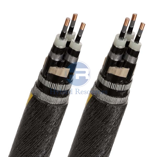
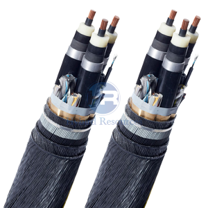
Three Core Steel wire armored Submarine Cable
Three Core Steel wire armored Submarine Cable Application
Three Core Steel wire armored Submarine Cable is is mainly intended for the solidly earthed system with power frequency 49~61Hz with rated voltage 35Kv and below, Used as high power electrical transmission between the mainland and the islands, island to island, mainland to the platform and between the offshore oil drilling platform, as well as control signals transmission of smart grid and communication signal transmission cross rivers, harbor, or the drilling platform or connection between drilling platforms, etc..
In general, the power transmission of submarine cable is undoubtedly more expensive than overhead cable with the same length, but it is more economic compare to using a small isolated power station to supply a region’s power, especially more benefits in the offshore area application.
The cable is widely used in Countries where have many islands and rivers.
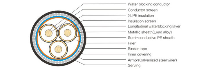
Three Core Steel wire armored Submarine Cable Construction

| Conductor | Water blocking stranded copper wire |
| Conductor screen | Semi-conductive compound |
| Insulation | XLPE |
| Insulation Screen | Semi-conductive compound |
| Water blocking tape | Semi-conductive tape |
| Matel Screen | Lead alloy |
| Sheath | HDPE |
| Filler | PE |
| Binder tape | Synthetic Tape |
| Inner Covering | PP yarns + Bitumen |
| Armoring | Galvanized steel wire |
| Serving | PP yarns + Bitumen |
Three Core Steel wire armored Submarine Cable Data
| Max.Allowable Conductor Working temperature | 90℃ |
| Short-circuit max.conductor temperature | 250℃ for 5 seconds |
| The lowest temperature while installing | 0℃ |
| Min.Bending radius | 15 times of actual cable outer diameter |
Three Core Steel wire armored Submarine Cable Specification
| Spec. | Current(A) | Resistant(Ω/km) | Capacitance | Design power (without consideration of power factor) |
Min. Bending Radius |
Cable
O.D |
Cable Weight In air |
|
| Nos*C.S.Area | Seabed/Beach/Land | 20℃ Max. DC |
90℃ Max. AC |
(μF/km) | (MVA) | (mm) | (mm) | (kg/km) |
| 3×50 | 232/209/173 | 0.387 | 0.494 | 0.203 | 3 | 1220 | 81.3 | 16375 |
| 3×70 | 282/253/209 | 0.268 | 0.342 | 0.222 | 3.6 | 1268 | 84.5 | 17831 |
| 3×95 | 337/301/248 | 0.193 | 0.247 | 0.246 | 4.3 | 1325 | 88.3 | 19584 |
| 3×120 | 381/340/280 | 0.153 | 0.196 | 0.272 | 4.8 | 1391 | 92.7 | 21658 |
| 3×150 | 425/379/312 | 0.124 | 0.159 | 0.295 | 5.4 | 1449 | 96.6 | 23765 |
| 3×185 | 477/424/349 | 0.0991 | 0.128 | 0.318 | 6 | 1506 | 100.4 | 25874 |
| 3×240 | 545/484/397 | 0.0754 | 0.098 | 0.35 | 6.8 | 1587 | 105.8 | 29043 |
| 3×300 | 606/573/440 | 0.0601 | 0.079 | 0.387 | 7.6 | 1682 | 112.1 | 32844 |
| 3×400 | 677/597/489 | 0.047 | 0.063 | 0.433 | 8.4 | 1797 | 119.8 | 38274 |
| 3×500 | 748/658/538 | 0.0366 | 0.05 | 0.473 | 9.3 | 1899 | 126.6 | 43390 |
DISCLAIMER: This is just part of the standard parameters of our products. Please contact our Engineer if you need more. And the information contained within this webpage is for guidance only and is subject to change without notice or liability. All dimensions and specifications are nominal and are subject to normal manufacturing tolerances. All pictures shown are for illustration purposes only. The actual product may vary. All the information is provided in good faith and is believed to be correct at the time of publication.


